Oldsmobility.com - Your 1967 Olds Cutlass / 442 Headquarters


Air Compressor Piping
Diagrams and Tips

by Keith Dickson
for OLDSmobility.com

     For the average do-it-yourselfer working at home in a small garage, air lines from the compressor are something not given a great deal of forethought, since most activities are not extremely air-intensive...that is, requiring a large volume of compressed air. For these people who might be occasionally using an air ratchet or inflating a tire or two, their portable compressor will work just fine and really require no additional planning. However, once you decide to really give your compressor a workout with a sandblaster, paint-gun or die grinder, the volume of air demanded by these tools require some rethinking in choosing an air compressor and how the air compressor's air lines are set up.

Choosing an Air Compressor

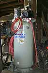
     The most commonly-made mistake is the purchase of a compressor which is too small for the work to be done. In figuring what size a compressor you'll need, do some research. A 60-gal upright compressor with a single-stage pump and a 5½-hp motor might seem like the ticket (or even a little bit of overkill) for the home user, but when you start looking at the CFM (cubic feet/minute) this compressor is capable of, you'll see that most are rated in the neighborhood of about 10-13 CFM, which for the most part is inadequate for sandblasting or painting. This type of compressor (pictured at right) is about the best single-stage compressor you're going to find, but a dual-stage compressor (with two pistons) will not have to work as hard, minimizing heat and water buildup in the compressed air. For the financially-impaired, the single-stage compressor CAN be made to work adequately, however...providing the user take frequent breaks to allow the compressor to catch up and to cool off. If the compressor is running full time, it's too small and will burn up in no time at all.

One of my favorite quotes, and one I TRY to live by, says:
"It's better to have it and not need it, than to need it and not have it".
This is especially applicable with air compressor selection. Always buy more compressor than you think you'll need, because if you have it, you WILL use it.

Air Compressor Piping Rules Of Thumb

  • After leaving the air compressor, air line pipe goes straight up the shop wall as high as possible. This helps minimize any water from leaving the compressor and traveling through the pipe.

  • Slope main lines at least four inches (10 cm) per 50 feet (12.7 m) of pipe away from air compressor so that condensate travels with the flow of air and away from the compressor. As warm air leaves the compressor, it cools and thereby condenses as it travels through the pipe. This water vapor, a problem in itself, can also cause scaling and rusting inside the piping. Install drop legs for condensate removal.

  • The first air drop should be at least 25 ft. (6.4 m) from the compressor although 50 feet (12.7 m) is optimum. This allows the compressed air to cool to room temperature so any condensation can occur before it gets into the water separator.

  • Take-off comes from the top of the main air supply line at each air drop. This reduces the risk of water and other contaminants from traveling down the drop into the water separator.

  • Use carbon steel pipe as discharge pipe material. Never use PVC or ABS. (PVC is easy to work with, but will not allow the hot air to cool quickly enough to condense the water in the compressed air. Also, in case of a compressor regulator failure, if the PSI inside the line were to go above the rated safety capacity, the plastic pipe won't just split, but will actually explode, producing razor-sharp projectiles which are sure to damage property and person.) Consider using Schedule 40 black iron, galvanized, copper, stainless steel, or anodized aluminum. Size the pipe for maximum CFM required. This will equal full load production plus future expansion plans. (See chart below)

    The size of the pipe is critical!
         Pipe diameter must be of sufficient size for the volume of air being passed as well as the length of pipe used. This will minimize pressure drop.
         Did you ever have only 60 or 70 pounds of pressure at the spray gun or other tool when your compressor should deliver 100 pounds? Using pipe that is too small in diameter can cause this pressure drop.
         For example, if an air compressor delivers 100 PSI through a 100 ft. pipe, 1/2-inch in diameter, there's greater pressure drop than if a 3/4-inch diameter pipe were used. Use the chart below to match your compressor's size and capacity with the optimum pipe size.

    DISCHARGE PIPE SIZE CHART
    Compressor
    Size
    Compressor
    Capacity
    Main
    Air Line
    Min. Pipe
    Diameter
    1½ & 2 HP 6 to 9 CFM Over 50 ft.

    ¾"

    3 & 5 HP 12 to 20 CFM Up to 200 ft. ¾"
    Over 200 ft. 1"
    5 to 10 HP 20 to 40 CFM Up to 100 ft. ¾"
    100 to 200 ft. 1"
    Over 200 ft. 1¼"
    10 to 15 HP 40 to 60 CFM Up to 100 ft. 1"
    100 to 200 ft. 1¼"
    Over 200 ft. 1½"

    Courtesy of DeVilbiss, an Illinois Tool Works Company


  • Use large enough pipe so as not to exceed 3 PSIG pressure loss through the entire line. (The target is a maximum 10% pressure drop through the entire system, i.e. from air compressor to farthest drop.)

  • Discharge pipe is to be the same size as air compressor outlet.

  • A shut-off valve should be installed before each point-of-use filter. This allows air supply to be shut off for filter maintenance.

  • Install a pipe tee in the discharge pipe to blow to atmosphere if necessary for control and adjustment. This will also serve as a convenient connection for a rental compressor if required.

  • Install pressure gauges throughout the system for troubleshooting. Locations should include the receiver, headers, tools, production equipment and the end of plant piping system.

  • Use long radius elbows. Try to use flow resistant fittings and valves. Use ball or butterfly valves.

  • Locate headers and sub-headers near air uses and manufacturing equipment. A loop system is ideal, providing two way flow distribution.

  • Do not connect multiple air users to the same drop. Use one drop for each air user.

  • Install an air receiver at intermittent high demand points such as occasional sandblasting, air motors, etc. Air receiver size should be one gallon of storage per 1 CFM of air compressor output as a minimum in order to permit the compressor controls to operate correctly.

  • Always consider leakage and future expansion in order to eliminate compressed air system obsolescence. A 10% per year growth rate is common.

  • Drain Valves: The daily draining of the system at each outlet disposes of the contaminants that build up in the air supply. Drain the compressor trap daily if equipped with a manual drain. Increase draining intervals appropriately during periods of heavy use.

  • Be sure to read and understand equipment instruction and installation manuals and discuss the layout and piping requirements before installation.

  • Proper maintenance of the air compressor can reduce airborne contaminants such as particles and oils, and reduce heat and operating cost. Check air filters, oil level and perform regular maintenance per operator's manual.

Sources:
- Ingersoll-Rand Company Booklet "The Compressed Air System, A Planning Workbook"
- DeVilbiss, an Illinois Tool Works Company

Air compressor piping layout 1

The following diagrams can be used in conjunction to the above tips for planning your piping layout. Click on each graphic to enlarge and use your browser's BACK button to return here.

Back Home

Using the diagrams and tips listed above, I designed and installed the following air compressor piping layout in my own garage, using ½" copper pipe. Compared with previous attempts at using PVC with no droplegs, the new layout works beautifully, and does an excellent job of filtering out every drop of moisture, ensuring my paint gun and sandblaster is only supplied with a steady stream of cool dry air. The droplegs catch 90%-95% of the moisture, allowing the water separators to easily remove anything remaining.

My Compressed Air Piping Layout

Back Home

Back to the top
| Home |
| My Personal Project - Photo Galleries | Updates/Journal | Sign My Guestbook | View My Guestbook |
| 1967 Specifications - Model ID | Product Specs | General Specs | Engine | Tune-up | Torque |
| Vintage Ads | Vintage Road Tests | Technical How-To's | Owner's Registry | Messageboard | Links |

line.gif (839 bytes)

Want to link to this site? Please use this banner.
OLDSmobility.com - The 1967 Olds Cutlass and 442 Resource

The correct URL for this website is http://www.OLDSmobility.com/)
For questions, comments or suggestions, please e-mail me.
All content on this site is © 1999-2008 by OLDSmobility.com/Project 442 Clone, unless otherwise noted. 
All rights reserved.
This page last modified on June 09, 2002.